CBSE Delhi-Set-3-2005
To Access the full content, Please Purchase
-
Q1
Name the appropriate communication channel needed to send a signal of band-width 100 kHz over a distance of 8 km. Marks:1View AnswerAnswer:
Coaxial cable can be used to send the desired signal. -
Q2
Give the direction in which the induced current flows in the coil mounted on an insulating stand when a bar magnet is quickly moved along the axis of the coil from one side to the other as shown in the figure.  Marks:1View Answer
Answer:
The current flows through the coil in different direction when magnet moves towards the coil and when it leaves the coil.
(i) When magnet moves towards the coil, the current flows in the clockwise direction (seen through right hand side).
(ii) When the magnet leaves the coil, the current flows in the anticlockwise direction (seen from the right hand side). -
Q3
Does the 'stopping potential' in photoelectric emission depend upon (i) the intensity of the incident radiation in a photocell? (ii) the frequency of the incident radiation? Marks:1View AnswerAnswer:
(i) No, the stopping potential does not depend upon the intensity of the incident radiation. (ii) Yes, the stopping potential depends upon the frequency of incident radiation. -
Q4
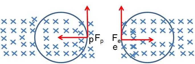
An electron and a proton, moving parallel to each other in the same direction with equal momenta, enter into a uniform magnetic field which is at right angles to their velocities. Trace their trajectories in the magnetic field. Marks:1View AnswerAnswer:
The trajectories of electron and proton will be circular and will have same radii but in opposite senses. The figure of the same is given below:
-
Q5
Define the term ‘dielectric constant’ of a medium. Marks:1View AnswerAnswer:
The dielectric constant of the medium may be defined as the ratio of force between two charged particles separated by a certain distance in air to the force between the same kept in given medium. -
Q6
Define ‘electric line of force’ and give its two important properties. Marks:2View AnswerAnswer:
Electric line of force may be defined as a curve which is drawn in such a manner that a tangent to it at any point gives the direction of the electric field at that point. Its two important properties are given as follows: 1. Two lines of forces can never intersect each other. 2. It is a continuous curve that starts from positive charge and ends on a negative charge. -
Q7
Draw V-I graph for ohmic and non-ohmic materials. Give one example for each. Marks:2View AnswerAnswer:
(i) The V-I graph for ohmic material is given below,
Metal is an example of ohmic material. (ii) The V-I graph for non-ohmic material is given below, 
Semiconductor is an example of non-ohmic material. -
Q8
Define the term ‘Magnetic Dip’ and ‘Magnetic Declination’ with the help of relevant diagrams. Marks:2View AnswerAnswer:
(i) Magnetic declination: The angle between the geometric meridian and magnetic meridian at a given place is called magnetic declination at that place. It is denoted by 
(ii) Angle of dip: It is the angle made by the earth’s total magnetic field with the horizontal at a given place. -
Q9
In the figure given below, a bar magnet moving towards the right or left induces an e.m.f. in the coils (1) and (2). Find giving reason, the directions of the direction of the induced currents through the resistors AB and CD when the magnet is moving (a) towards the right, and (b) towards the left. 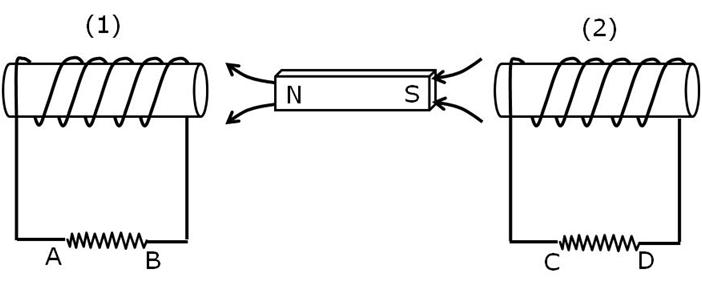 Marks:2View Answer
Answer:
(a) When the magnet moves in the right hand side, the right end of the coil 1 and left end of coil 2 develops S-polarity. This results in flow of current in anticlockwise direction in both the coils. Hence current in coil 1 flows from A to B while in coil 2 it flows from D to C.
(b) When the magnet moves towards the left hand side, the right end of coil 1 and left end of coil 2 develops N-polarity. This results in flow of current in clockwise direction on both the coils. Hence current in coil 1 flows from B to A while in coil 2 it flows from C to D. -
Q10
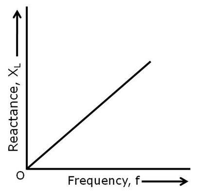
(i) Draw the graphs showing variation of inductive reactance and capacitive reactance with frequency of applied a.c. source.
(ii) Can the voltage drop across the inductor or the capacitor in a series LCR circuit be greater than the applied voltage of the a.c. source? Justify your answer. Marks:2View AnswerAnswer:
(i) The variation of inductive reactance with frequency is given below,
The variation of capacitive reactance along with frequency is given below, 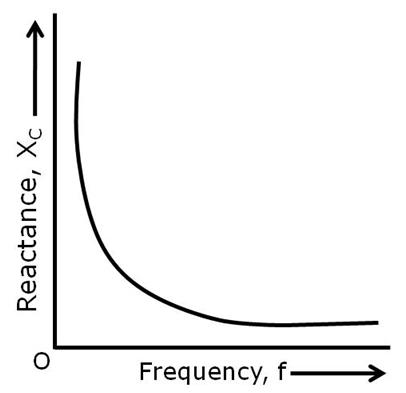
(ii) Yes, the variation of voltage drop across the capacitor or inductor can be greater than the applied voltage. This is because the voltage across capacitor or inductor is not in same phase and they cannot be added like ordinary numbers.